
- Dynamic fatigue testing machine
- Friction and wear testing machine
- Fastener special testing machine
- Static mechanical property testing machine
- In-situ tensile testing machine
- Non-standard customized large and small mechanical equipment
- Metallographic sample preparation and analysis equipment
- hardmeter
- Solution of overall design and planning of laboratory
LZW-1 Computer-controlled wheeled indoor weighted fatigue testing machine for sale
Computer-controlled wheel indoor weighted fatigue testing machine is used to simulate the repeated loading test of wheels on road paving materials such as cement under indoor conditions, so as to determine its fatigue life and provide data support for material performance evaluation.
Introduction
1.1 The test equipment consists of a main machine and a control cabinet. The main machine adopts a small gantry platform structure, and the loading frame moves in space. As can be seen from the diagram, the main engine consists of three parts: the base, the movable loading frame and the reciprocating power mechanism. Linear guide rails are installed on both sides of the abutment, and the mobile loading frame is installed on four sliding blocks through pillar fixing seats. One side of the left and right pillar fixing seats is connected by a connecting piece. The piston rod of the reciprocating electric cylinder is connected with the connecting piece, which can drive the whole loading mechanism to move back and forth.
1.2 The movable loading frame is composed of the upper fixed top plate, two pillars, movable cross beam, pillar fixing seat, loading linear electric cylinder, load sensor and other parts. The fixed top plate and the pillar fixing seat form a square frame through two pillars, and the loading electric cylinder is installed between the fixed top plate and the moving cross beam, and the moving cross beam can be driven to move up and down along the pillars through sliding guide sleeves through the expansion and contraction of the electric cylinder.
1.3 The loading wheel is installed on the lower surface of the mobile beam, and the mobile beam moves along the column through the telescopic traction of the electric cylinder. So that a squeezing load is formed between the loading wheel and the test piece.
1.4 The whole machine has simple structure, high integration, high strength and small deformation;
Parameters
|
Category |
Parameter |
Specification |
|
2.1 Loading System |
Vertical Load |
0 ~ 2000 N, continuously adjustable. |
|
|
Load Accuracy |
Within ±1% of indicated value. |
|
|
Load Resolution |
≤ 1 N. |
|
|
Loading Method |
Rolling wheel loading, stable loading trajectory ensuring uniform force on the specimen surface. |
|
|
Loading Frequency |
0.5 ~ 5 Hz adjustable, frequency stability error ≤ ±5% of the set value. |
|
2.2 Motion System |
Travel Mode |
Drive wheel performs reciprocating linear motion on the specimen surface. |
|
|
Travel Stroke |
0 ~ 300 mm adjustable, to accommodate specimens of different sizes. |
|
|
Stroke Accuracy |
±1 mm. |
|
|
Drive Method |
Servo motor drive, ensuring smooth motion, rapid response, and low noise. |
|
2.3 Specimen & Fixture |
Specimen Size |
300mm (L) × 300mm (W) × 50-100mm (H). |
|
|
Fixture Requirement |
Equipped with dedicated, adjustable specimen clamping device to ensure firm fixation during testing. |
LGP-100 High frequency fatigue testing machine
LGP series high-frequency fatigue testing machine represents...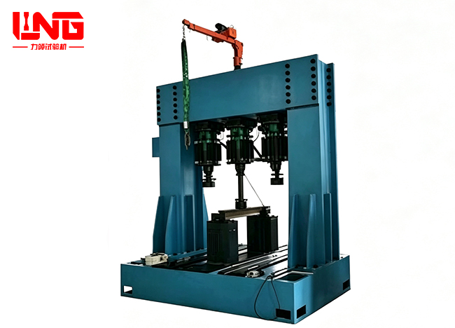
LPM-500S-3 Electro-hydraulic pulsating fatigue testing machine
LPM-500S-3 Electro-hydraulic pulsating fatigue testing machi...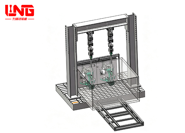
PLS-W25 Four Channel Electro Hydraulic Servo Air Spring Fatigue Test System
The PLS-W25 four channel electro-hydraulic servo air spring ...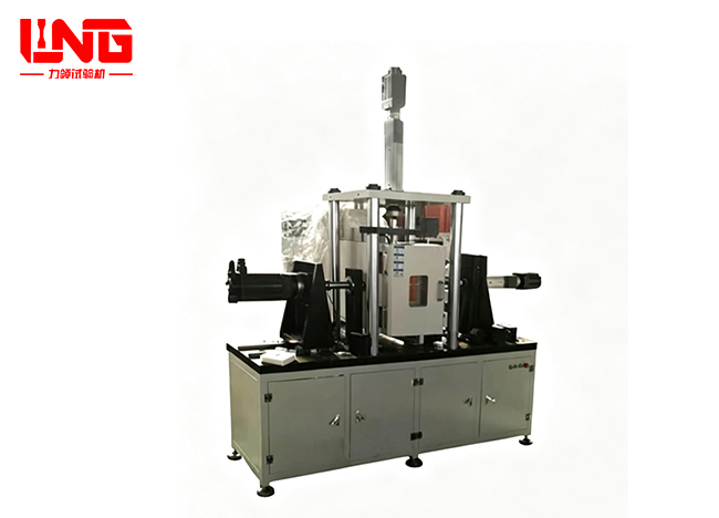
LB-RBT-2025Rubber lining comprehensive performance test bench
Rubber bushings are key elastic components of automotive cha...
Wheel high-speed durability testing machine
This plan is designed to meet the high-speed performance tes...
Microcomputer-controlled automobile air spring tension and compression testing machine
The air spring tension and compression tester is a high-perf...
YAW-5000F Computer-controlled Electro-hydraulic Servo Jack Testing Machine
The YAW-5000F microcomputer controlled electro-hydraulic ser...
PWS-1000CQ comprehensive performance testing platform for drive axle housing
The comprehensive performance testing platform for the drive...
About LiLing
Product range
News
Contact LiLing
Address:山东省济南市市中区魏华西路6号院内2号厂房


Business consultation (WeChat)